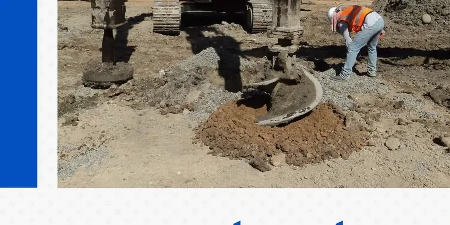
The vibroflot is a long cylindrical probe, about 12 to 16 inches in diameter, powered by an electric or hydraulic motor that generates horizontal vibrations. In Jacksonville, this equipment gets lowered into the ground with water or air jetting assistance, creating a borehole that is then backfilled with clean crushed stone in controlled lifts. The process builds a dense, load-bearing column that reinforces the surrounding soil matrix. Jacksonville’s coastal plain geology, with its layers of loose fine sands and pockets of organic silt near the St. Johns River, responds well to this technique because the vibrations simultaneously densify the in-situ granular material while the stone column provides vertical drainage and stiffness. Before mobilization, the team defines column diameter, grid spacing, and depth based on a comprehensive site investigation that often includes a CPT test to map stratigraphy continuously and identify the compressible layers that control settlement performance.
A stone column grid can cut total settlement by half or more in the loose sands common beneath Jacksonville’s coastal plain.
Local geotechnical context
Jacksonville sits on the Hawthorn Group and overlying Quaternary sediments: the surficial sands can have SPT blow counts as low as N=4 to N=8, and the water table is shallow, often within three feet of the surface in the low-lying areas west of the Intracoastal Waterway. Designing stone columns without adequate site data is risky: if a buried lens of very soft organic clay goes undetected, the columns can punch through it, transferring stress to a weaker layer and causing differential settlement that can crack slab-on-grade foundations. The other major failure mode is bulging near the top of the column in the active zone, where lateral confinement is minimal. To mitigate this, the upper portion of each column is constructed with a larger diameter or a gravel blanket is placed over the grid to distribute load and resist lateral spreading. A thorough review of the geotechnical report is non-negotiable; the design must be calibrated to the specific stratification found across the site, not just a single boring log.
Questions and answers
Is stone column design suitable for the high-water-table conditions in Jacksonville?
Yes. The vibro-replacement method is specifically suited for sites with shallow groundwater because the column is built from the bottom up inside a borehole that is kept open by the vibratory probe and water pressure. The stone is compacted in lifts, and the surrounding soil is simultaneously densified. This process works well in the loose sands and low-plasticity silts found across Jacksonville, where water is often encountered within the first few feet of excavation.
What does stone column design cost for a commercial building in Jacksonville?
For a commercial project in Jacksonville, the engineering design and construction verification for a stone column ground improvement program typically ranges from US$1,560 to US$5,840. The total project cost depends on the treated area, column depth, grid density, and the number of post-installation load tests required. We provide a detailed proposal after reviewing the geotechnical baseline report and the structural loading plan.
How do you verify that the stone columns are performing as designed?
Verification follows a two-stage approach. First, we run CPT soundings or SPT borings in the center of the grid cell after installation to measure the increase in tip resistance and sleeve friction. Second, we perform a modulus load test on a sacrificial column using a reaction frame to measure load-deflection behavior. The results are compared directly against the settlement and bearing capacity values used in the design model.